
Wiring a tri-color LED driver to work with a dimmer switch or remote control requires matching the driver’s specific dimming protocol with your control interface, routing the electrical current safely, and correctly mapping the multi-channel output wires to the light fixture. Tri-color LED fixtures achieve different color temperatures—typically warm white, neutral white, and cool white—by mixing current between two distinct sets of LED chips. To control both brightness and color temperature smoothly, you must install a compatible control system, whether that is a mains-voltage wall dimmer or a low-voltage wireless receiver.
Successfully executing this installation depends on understanding the electrical pathway from your home’s mains power supply to the driver, and finally to the light fixture itself. Incorrect wiring can cause permanent damage to the driver, result in persistent flickering, or create serious electrical hazards. By following systematic verification and connection steps, you can safely achieve seamless control over your space’s ambiance.
Electrical Safety Boundaries and Tool Checklist
Working with electrical wiring carries inherent risks of severe shock or electrical fire. Before touching any wires or removing existing fixtures, you must isolate the electrical circuit by turning off the correct miniature circuit breaker (MCB) at your home’s main distribution board (DB box). Simply turning off the wall switch is insufficient, as live current can still be present at the switch box or light point.
Products mentioned in this guide
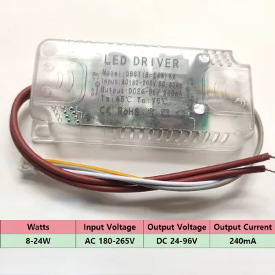
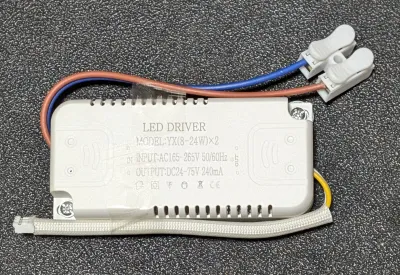
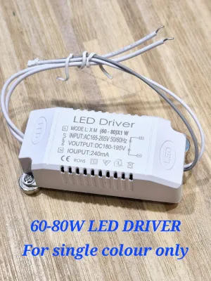
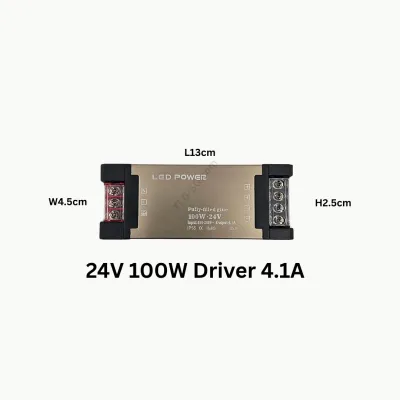
Prices are valid at publication and may change. Please refer to the product page for the latest price.
Once the breaker is switched off, use a reliable non-contact voltage tester to verify that the wires are completely dead. Test the tool on a known live source first to ensure it is functioning correctly, then test the wires you intend to handle. Never touch any copper conductor until you have confirmed the complete absence of voltage.
In Singapore, strict electrical regulations govern residential wiring. Under local energy regulations, any complex fixed electrical wiring, installation of new circuits, or modifications to the main distribution board must be performed by an Energy Market Authority (EMA) licensed electrician to comply with the SS 638 code of practice. If your installation involves running new cables behind walls or modifying your DB box, you must engage a qualified professional.
To complete this installation safely and efficiently, gather the following essential tools:
- A certified non-contact voltage tester
- High-quality wire strippers capable of handling standard residential wire gauges
- Insulated screwdrivers rated for electrical work
- Appropriate wire connectors, such as lever-lock connectors or screw terminals rated for 230V AC
You must stop the installation immediately and consult a licensed professional if you encounter any of the following conditions:
- The existing junction box lacks an earth/ground wire
- Any wires show signs of heat damage, melting, or brittle insulation
- You cannot confidently identify which wires are the live feed (Line) and which are the switched load
- The physical space inside the wall box or ceiling cavity is too cramped to house the driver safely without pinching wires
Verifying Driver, Dimmer, and Remote Compatibility
Before mounting any hardware, you must verify that your tri-color LED driver, dimmer switch, or remote control system are electrically compatible. Standard on/off wall switches do not dim lights; instead, some specialized tri-color drivers use rapid power toggling to cycle through pre-set color temperatures. True continuous dimming requires a dedicated dimmer switch that matches the driver’s dimming technology.

For wall-mounted dimmers, the most common residential technology is phase-cut dimming. LED drivers generally require trailing-edge (sometimes called reverse-phase) dimmers, which cut off the end of the AC sine wave to provide smooth, silent dimming without causing the driver to buzz or overheat. Check the technical specifications of both your driver and your dimmer switch to confirm they are explicitly rated to work together.
In Singapore, the mains electricity supply is 230V AC at 50Hz. Ensure your tri-color LED driver is rated for this input voltage. Additionally, check the driver’s DC output specifications—such as whether it is a constant current (CC) or constant voltage (CV) driver—and ensure the total wattage of your connected LED fixture does not exceed 80% of the driver’s maximum rated wattage to allow a safe operating margin.
If you prefer wireless control, you must identify the communication protocol used by your remote system. Remote-controlled setups typically fall into three categories:
- Radio Frequency (RF) or Infrared (IR): These systems use a physical hand-held remote that communicates with an inline receiver module wired directly before or integrated into the driver.
- Smart Home Protocols (Zigbee or Z-Wave): These require a compatible smart hub to translate signals from wireless switches or mobile apps.
- Wi-Fi Direct: These drivers connect directly to your home's 2.4GHz wireless network and do not require a separate physical receiver.
Always consult the manufacturer’s wiring schematic before making any connections. The diagram on the driver’s casing will indicate the exact terminal assignments for the AC input side (typically labeled L for Live, N for Neutral, and an Earth symbol) and the DC output side (which will feature multiple terminals for the different color channels).
Step-by-Step Wiring for an LED Dimmer Switch
Connecting an LED-compatible wall dimmer to your tri-color driver requires careful routing of the mains power through the switch before it reaches the driver’s input terminals.
Step 1: Prepare the Installation Site Ensure the main circuit breaker is off and verify the absence of voltage with your tester. Remove the existing wall switch plate carefully, exposing the wires inside the junction box. Take a clear photograph of the original wiring configuration for reference before disconnecting any wires.
Step 2: Connect the Mains to the Dimmer Identify the incoming live wire from the DB box (typically colored brown in modern Singaporean installations, or red in older properties) and connect it to the input terminal of the dimmer switch, often labeled “L” or “Line”. Connect the output wire (often labeled “Load”, “L1”, or indicated by a wave symbol with an arrow) to the wire that runs through the conduit to your ceiling light point. If you are using a smart dimmer that requires a neutral wire, connect the incoming neutral wire (blue or black) to the dimmer’s “N” terminal.
Step 3: Connect the Dimmer Output to the LED Driver At the ceiling light point, locate the switched live wire coming from the dimmer switch. Connect this switched live wire to the “L” (Live) terminal of the tri-color LED driver’s AC input. Connect the mains neutral wire (blue) directly to the “N” (Neutral) terminal of the driver. Secure the green/yellow earth wire to the driver’s grounding terminal if the driver features a metal housing; if the driver is double-insulated (Class II) and lacks a ground terminal, terminate the earth wire safely in an isolated connector block.
Step 4: Connect the Driver to the LED Fixture Tri-color LED fixtures utilize a multi-wire DC connection to control the individual warm white and cool white LED channels. The output side of the driver will typically have three terminals or wires: a common positive (often labeled V+ or COM) and two separate negatives (labeled CW- for cool white and WW- for warm white). Connect these to the corresponding terminals on the LED fixture, ensuring absolute polarity matching. If the wires are crossed, the light will either fail to illuminate or the color temperature control will be reversed.
Step 5: Secure and Inspect Ensure all wire connections are tight and fully insulated inside approved connector blocks, leaving no bare copper exposed. Gently fold the wires into the junction boxes, taking care not to pinch the insulation, and mount the dimmer switch and driver securely. If you find that the wire colors in your wall do not match standard conventions, or if the terminal markings on your driver are ambiguous, stop immediately and contact a licensed electrician.
Setting Up a Remote Control or Smart Receiver
Wireless control systems bypass the need for physical control wiring between the wall switch and the light fixture by using a receiver module to intercept and process control signals.
When installing a remote-controlled system, the receiver module must be physically positioned along the electrical pathway. For external receiver systems, the module is placed between the 230V AC mains supply and the LED driver’s input. For integrated smart systems, the receiver is built directly into the driver housing, simplifying the physical footprint.
To wire an external wireless receiver, connect the mains Live (brown) and Neutral (blue) wires directly to the “AC Input” terminals of the receiver. Next, run a short length of suitable cable from the receiver’s “AC Output” terminals to the “AC Input” (L and N) terminals of your tri-color LED driver. This allows the receiver to switch or modulate the power flowing into the driver based on commands from your remote control.
Once the physical wiring is complete and safely enclosed, restore power at the circuit breaker to begin the pairing process. Most RF or IR remotes require you to hold down a specific button (often the power button or a dedicated pairing key) within a few seconds of switching on the mains power. Refer to your product’s manual for the exact timing and button sequence to sync the remote with the receiver.
If you are setting up a smart Wi-Fi or Zigbee-enabled driver, the pairing process is digital. Ensure your mobile device is connected to a compatible 2.4GHz Wi-Fi network, open the manufacturer’s designated smart home app, and set the driver into pairing mode—usually achieved by toggling the physical wall switch on and off several times in quick succession. Follow the on-screen prompts to discover and register the device.
Before closing the ceiling canopy or junction box, double-check that all wire nuts or lever connectors are locked tight. Ensure the driver and receiver are positioned away from direct contact with thermal insulation, allowing adequate air circulation to prevent heat buildup in Singapore’s warm climate.
Testing the Circuit and Troubleshooting Common Issues
With all components securely wired and mounted, you can safely restore power at the main distribution board to test the functionality of your new lighting system.
Begin your initial test by turning the light on at its lowest brightness setting, then gradually increase it to maximum. Cycle through the different color temperatures using your remote control, app, or wall switch to ensure the transitions from warm white to cool white are smooth and that both channels illuminate correctly. If the colors do not mix properly, or if only one color temperature works, turn off the power and check the DC output connections between the driver and the fixture.
If you experience persistent flickering or a buzzing sound when dimming, the issue is usually caused by an electrical mismatch. Flickering often occurs if the minimum wattage load of your dimmer switch is higher than the total wattage consumed by your LED fixture. To resolve this, you can replace the dimmer with a model that has a lower minimum load threshold, or adjust the dimmer’s lower-limit calibration dial (if equipped) to prevent the power from dropping below the driver’s stable operating level.
When troubleshooting an unresponsive remote control, check the simple physical factors first. Replace the batteries in the transmitter, ensure there are no physical obstructions blocking the path if using an IR system, and verify that the receiver’s antenna wire is not bent or shielded inside a metal junction box. For smart app controls, ensure your home router is not overloaded with connected devices and that the driver is within stable wireless range.
Perform a final physical inspection of the installation site. Ensure the LED driver is housed in a dry, well-ventilated location, as excessive ambient heat can drastically shorten the lifespan of electronic components. Verify that all faceplates are screwed on straight and that the light fixture is securely anchored to the ceiling structure to prevent any risk of falling.
Frequently Asked Questions (FAQ)
Can I use a standard incandescent dimmer switch with a tri-color LED driver?
No, you should not use a standard incandescent dimmer switch with a tri-color LED driver. Traditional dimmers typically use leading-edge phase cutting, which is designed for resistive loads like incandescent bulbs and can cause modern capacitive LED drivers to flicker, buzz loudly, or fail prematurely. You must use an LED-compatible trailing-edge dimmer that matches the specific input requirements of your tri-color driver.
Why does my tri-color LED change color when I use a normal wall switch?
This behavior occurs because your LED driver features a built-in step-dimming or color-cycling memory function. When you toggle a standard on/off wall switch quickly, the driver detects the brief interruption in power and automatically switches the internal circuit to the next color temperature channel. This built-in mechanism allows color switching without a dedicated remote control, but it does not provide smooth, continuous dimming control.
Community discussion
Share your experience or ask a question. Comments are reviewed before publication.