
To determine if a led driver 24w is compatible with your dimmer switch, you must verify three critical factors: the driver must be explicitly labeled as dimmable, its dimming protocol (such as TRIAC or 0-10V) must match the dimmer switch’s control method, and the 24W power draw must fall within the dimmer’s minimum and maximum LED load ratings. Ignoring these parameters often leads to rapid flickering, audible buzzing, or permanent damage to the driver and connected LED fixtures.
An LED driver acts as the heart of your low-voltage lighting system, converting high-voltage alternating current (AC) from your home’s mains supply into the stable, low-voltage direct current (DC) required by LED chips. While traditional incandescent bulbs dim simply by reducing voltage, LEDs are highly sensitive semiconductor devices that require precise current control. If you attempt to dim a non-dimmable driver, or pair a dimmable driver with an incompatible switch, the driver’s internal circuitry will struggle to interpret the chopped electrical signal, resulting in poor performance and a significantly shortened lifespan.
Achieving smooth, flicker-free dimming down to low levels requires a systematic check of your components. By verifying the electrical specifications, matching the control protocols, and respecting load boundaries, you can ensure a safe and reliable lighting setup.
Products mentioned in this guide
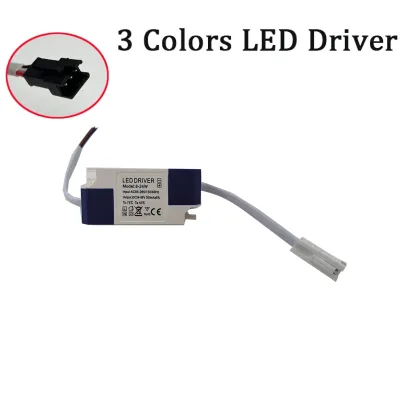
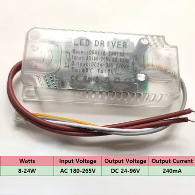
Prices are valid at publication and may change. Please refer to the product page for the latest price.
Step 1: Check the Electrical Specifications of Your LED Driver 24W
Before analyzing dimming compatibility, you must confirm that the basic electrical parameters of your driver and dimmer match your local electrical infrastructure. In Singapore, the standard utility grid delivers electricity at 230V AC at a frequency of 50Hz. You must inspect the physical nameplate or official datasheet of both your dimmer switch and the led driver 24w to ensure they are rated to handle this input voltage safely. A driver designed solely for a 120V market will fail immediately and pose a safety hazard if connected to a 230V line.
Next, examine the output specifications printed on the driver. A 24W driver typically outputs either a constant voltage (commonly 12V DC or 24V DC) or a constant current (measured in milliamperes, such as 350mA or 700mA). For example, a 24W constant-voltage driver operating at 24V DC can safely deliver a maximum current of 1.0A to your LED strips. You must verify that these output metrics perfectly match the requirements of your light fixture; a mismatch here will prevent the lights from illuminating or cause immediate burnout, regardless of the dimmer switch you use.
Never rely on generic category names or retail descriptions to assume compatibility. Always locate the physical label on the device housing to confirm the exact model numbers, input/output ranges, and safety certifications. If the label is missing, illegible, or lacks clear specifications, do not attempt installation; consult the manufacturer’s technical documentation to verify the parameters.
Step 2: Match the Dimming Protocol
For successful dimming, the dimmer switch and the LED driver must communicate using the exact same electrical protocol. If the switch sends a signal that the driver cannot interpret, the system will fail to dim correctly. There are three primary dimming protocols used in residential and commercial lighting systems.

TRIAC (Phase-Cut) Dimming
TRIAC dimming, also known as phase-cut dimming, is the most common protocol found in standard residential wall switches. This method works by chopping out portions of the AC voltage waveform to reduce the total power delivered to the light source.
- Leading-Edge (Forward Phase): Traditionally used for incandescent and halogen lamps, leading-edge dimmers cut off the front portion of each AC wave. These are generally incompatible with low-wattage LED drivers unless both devices are explicitly rated for forward-phase LED loads.
- Trailing-Edge (Reverse Phase): Designed specifically for electronic low-voltage (ELV) loads, trailing-edge dimmers cut off the trailing part of the AC wave. This provides a much smoother start and is highly recommended for LED drivers.
- Driver Labeling: To use a TRIAC dimmer, your 24W driver must be explicitly marked as "TRIAC Dimmable," "Phase-Cut," "Leading/Trailing Edge Compatible," or "ELV Dimmable."
0-10V and 1-10V Dimming
Commonly utilized in commercial spaces and modern architectural residences, 0-10V dimming is an analog protocol that relies on a dedicated low-voltage control signal separate from the main power lines.
- Wiring Requirements: This system requires two additional low-voltage control wires (usually colored purple and grey or pink) running directly from the dimmer switch to the driver.
- Signal Control: The dimmer sends a variable DC voltage signal between 0V (or 1V) and 10V to tell the driver how bright to run. A signal of 10V represents maximum brightness, while 1V or 0V represents the lowest dimmed state or complete shutdown.
- Compatibility Check: Both your dimmer switch and your 24W driver must feature dedicated 0-10V control terminals to function. A standard two-wire wall dimmer cannot control a 0-10V driver.
PWM and Smart/Digital Protocols
Pulse Width Modulation (PWM) and digital protocols represent advanced methods where brightness is adjusted by rapidly switching the LED current on and off at high frequencies invisible to the human eye.
- Smart Modules: Systems using Zigbee, Bluetooth, or DALI (Digital Addressable Lighting Interface) require a driver with an integrated digital receiver or a compatible external controller.
- Digital Communication: The dimmer switch in these setups does not directly alter the electrical current; instead, it sends a digital command to the driver, which then uses internal PWM to dim the LEDs.
- Verification: Ensure your smart hub or wireless dimmer switch uses the identical wireless standard (such as Zigbee 3.0) supported by the driver.
Step 3: Verify Minimum and Maximum Load Requirements
Every dimmer switch has an operational wattage range that must be respected to maintain circuit stability. While users often focus on the maximum load limit to prevent overloading the switch, the minimum load limit is equally critical and frequently overlooked when dealing with low-wattage setups like a 24W system.
Older dimmer switches designed for incandescent bulbs often carry a high minimum load requirement, such as 40W or 60W. If you connect a single 24W LED driver to such a switch, the total power draw falls well below the dimmer’s operational threshold. This lack of resistance prevents the dimmer’s internal components from firing correctly, resulting in severe flickering, strobing, or a complete failure of the light to turn on.
To avoid this issue, always check the dimmer’s specific “LED load” rating rather than its incandescent rating. A modern, LED-compatible dimmer will typically specify a very low minimum load (often starting at 0W or 5W) and a maximum LED load rating (such as 150W). Ensure that your 24W driver’s total power draw sits comfortably within this specified window.
Troubleshooting Common Compatibility Issues
Even when specifications appear to match on paper, real-world installations can sometimes exhibit performance anomalies due to minor component variances. Understanding these symptoms helps you diagnose and resolve issues quickly.
- Flickering or Strobing at Low Levels: This behavior usually points to a minimum load issue or a phase-cut mismatch. If the flickering occurs only when the light is dimmed below 20%, the dimmer may be dropping below its minimum stable voltage. Adjusting the dimmer's low-end trim (a physical dial or digital setting on many modern switches) can establish a higher minimum brightness floor to prevent this drop.
- Audible Buzzing or Humming: A physical hum coming from the driver or the switch indicates rapid mechanical vibration caused by sharp voltage spikes. This is highly common when pairing a leading-edge TRIAC dimmer with an electronic driver. Replacing the switch with a high-quality trailing-edge (ELV) dimmer typically resolves the vibration.
- Lights Not Turning Off Completely (Ghosting): Some smart dimmers require a tiny trickle of electrical current to pass through the circuit even when turned "off" to keep their internal wireless chips powered. Because LEDs are highly efficient, this leakage current can cause your lights to glow faintly in the dark. Installing a compatible bypass resistor across the load side of the driver, or switching to a smart dimmer that utilizes a dedicated neutral wire, will eliminate ghosting.
Safety and Installation Boundaries
Working with residential electrical systems carries inherent risks of electrical shock, fire, and equipment damage. Prioritizing safety is paramount before attempting any physical installation or diagnostic work on your lighting system.
Always isolate the electrical power at your home’s main distribution board (DB box) by switching off the corresponding circuit breaker before touching any wiring. Verify that the power is fully off using a reliable, non-contact voltage tester at the switch box. Never bypass safety grounding, fuses, or circuit breakers in an attempt to make an incompatible driver work.
In Singapore, fixed electrical wiring installations must comply with local safety standards. If your installation involves running new wire paths, working at heights, retrofitting damp areas, or if you discover that your switch box lacks a neutral wire (which many modern smart dimmers require), you must stop and consult a licensed electrical worker (LEW) registered with the Energy Market Authority (EMA). Professional installation ensures compliance with local codes and protects your home’s warranty and insurance coverage.

Community discussion
Share your experience or ask a question. Comments are reviewed before publication.