
Adding dimming or remote control to your LED light strips can instantly transform a room’s atmosphere, shifting it from bright task lighting to a soft, relaxed glow. However, achieving smooth, flicker-free dimming requires matching your control hardware with your power supply. You can use a dimmer or a remote controller with an LED light strip driver, but your setup depends entirely on whether you control the power on the high-voltage AC side (before the driver) or the low-voltage DC side (after the driver).
Pairing incompatible components is a common DIY lighting mistake that leads to buzzing, strobing, or permanent electrical damage. To ensure a safe and successful installation, you must verify the specifications of your led light strip driver, understand the mechanics of AC-side and DC-side control, and follow proper wiring protocols.
Check Compatibility: Is Your LED Light Strip Driver Dimmable?
Before purchasing a wall dimmer or a remote control, you must determine whether your existing or planned power supply supports dimming. An LED light strip driver acts as the intermediary between your home’s high-voltage alternating current (AC) grid and the low-voltage direct current (DC) required by the LED strips.
Products mentioned in this guide
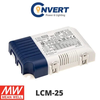
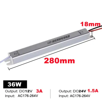
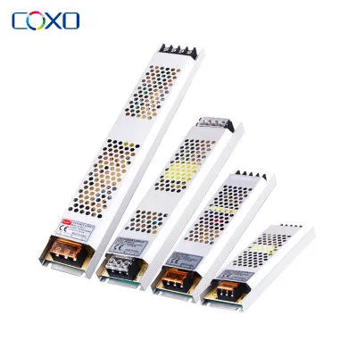
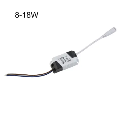
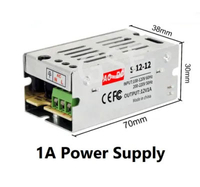
Prices are valid at publication and may change. Please refer to the product page for the latest price.
To check compatibility, inspect the physical label printed on the driver’s housing or consult its specification sheet. Look for explicit terms like “Dimmable,” “TRIAC Dimmable,” “Phase-Cut Dimmable,” “0-10V,” or “PWM Compatible.” If the label does not state that the unit is dimmable, you must assume it is a standard, non-dimmable driver.
The fundamental difference lies in the internal circuitry. A standard, non-dimmable driver is engineered to deliver a highly stable, constant output voltage (typically 12V or 24V DC) regardless of minor fluctuations in the input power. If you attempt to restrict its incoming AC power using a wall dimmer, the driver’s internal components will actively fight the voltage drop to maintain its rated output. This conflict causes severe electrical stress, resulting in visible flickering, loud buzzing, excessive heat, and eventual failure of both the driver and the LED strips.
Conversely, a dimmable driver is designed to interpret a modified input signal—such as a chopped AC sine wave from a phase-cut wall dimmer—and translate that into a corresponding reduction in the output voltage or current delivered to the LEDs. Knowing your driver type is the crucial first step that dictates your entire installation path.
AC-Side vs. DC-Side Control: Choosing the Right Pairing
When planning your dimming setup, you must choose between controlling the power on the AC input side of the driver or the DC output side. Each method has distinct hardware requirements and practical use cases.

AC-Side (Primary) Dimming AC-side dimming involves placing a standard wall dimmer switch on the mains power line before it reaches the driver. In this configuration, the dimmer chops the 230V AC mains voltage, requiring an AC-dimmable driver to translate this chopped signal. This method is highly favored for architectural lighting because it allows you to control your LED strips using the same physical wall switches as your traditional ceiling lights, maintaining a clean, integrated look without requiring external receivers or handheld remotes.
DC-Side (Secondary) Control DC-side dimming leaves the incoming AC mains power completely untouched. The driver receives a constant, full-voltage AC input and outputs a steady 12V or 24V DC supply. The dimming or control hardware—such as an RF receiver, an IR receiver, a smart home controller, or a manual inline dial—is wired on the low-voltage side, positioned directly between the driver’s DC output and the LED strip. This controller dims the lights by rapidly switching the DC power on and off at a high frequency, a process known as Pulse Width Modulation (PWM). Because the driver itself does not need to dim, you can use a standard, non-dimmable driver for this setup.
A Quick Decision Framework To choose the right pairing for your home, consider your control preferences:
- Choose AC-Side Dimming if you want to control your lights using a physical wall switch, integrate them with existing wall-dimmer circuits, or maintain a seamless, hardware-free aesthetic.
- Choose DC-Side Dimming if you want to use a handheld remote control, adjust colors on RGB or RGBW multi-color strips, connect your lighting to a smart home app, or if you are working with an existing non-dimmable driver.
How to Wire a Wall Dimmer to an AC-Dimmable Driver
If you have decided on AC-side dimming with an AC-dimmable driver, you must follow a precise installation sequence to ensure safety and proper functionality. Because this process involves handling high-voltage mains electricity, safety must be your absolute priority.
Step 1: Isolate the Power Before touching any electrical wiring, go to your home’s main distribution board (DB box) and switch off the circuit breaker for the lighting circuit you will be working on. Use a certified non-contact voltage tester at the wall switch box and the driver location to verify that no electrical current is flowing through the wires.
Step 2: Wire the AC Dimmer Switch Connect the physical wall dimmer switch in series along the live wire of the incoming AC mains supply. The live wire coming from the DB box connects to the input terminal of the dimmer switch, while the load wire runs from the dimmer’s output terminal to the Live (L) terminal on the AC input side of the dimmable driver. Connect the Neutral (N) wire directly from the mains supply to the Neutral terminal on the driver. If your driver or switch housing is metal, ensure the Earth (E) wire is securely connected to the grounding terminal.
Step 3: Connect the DC Output With the high-voltage side wired, move to the low-voltage output side of the driver. Connect the positive output wire (typically red or labeled V+) to the positive terminal pad on your single-color LED light strip. Connect the negative output wire (typically black or labeled V-) to the negative terminal pad on the strip. Ensure all terminal screws are tightened securely to prevent loose connections.
Step 4: Restore Power and Calibrate Once all connections are insulated and secured, switch the mains power back on at the DB box. Turn on the wall dimmer and test the full dimming range. If your wall dimmer has a minimum trim adjustment setting, adjust it upward if you notice the LED strip flickering or shutting off at low dimming levels, ensuring the light remains stable at its lowest point.
Singapore Electrical Safety Boundary Working with 230V AC mains electricity carries inherent risks of severe shock or electrical fire. In Singapore, all fixed electrical installation work must comply with local safety standards, specifically SS 638. If you are replacing a standard wall switch with a dimmer, modifying your home’s fixed wiring, or if you feel any uncertainty, you must hire a licensed electrical worker (LEW) to perform the installation.
How to Set Up a Remote Controller on the DC Side
Setting up a remote control or smart receiver on the low-voltage DC side is a popular DIY project because it operates at safe voltages (usually 12V or 24V) and allows for advanced features like color changing, zoning, and wireless scheduling.
Step 1: Connect Driver Output to Controller Input Ensure the mains power to the driver is turned off before making any connections. Identify the low-voltage output terminals on your standard, non-dimmable driver. Run a pair of low-voltage wires from the driver’s positive (V+) and negative (V-) terminals to the corresponding DC input terminals on your remote receiver or smart controller. Pay close attention to polarity; reversing the positive and negative connections can instantly destroy the controller.
Step 2: Connect Controller Output to the LED Strip Next, connect the output terminals of the controller to the input pads of your LED light strip. For single-color strips, connect the positive (+) and negative (-) wires from the controller output to the corresponding pads on the strip. For multi-color strips (RGB/RGBW), carefully match the common positive wire (often labeled V+ or +) and the individual color channel wires (labeled R for Red, G for Green, B for Blue, and W for White) from the controller output to the exact matching pads on the LED strip.
Step 3: Pair and Test the System Turn on the mains power to the driver. The driver will output a steady DC voltage to the controller. Follow the manufacturer’s pairing instructions to link your handheld RF or IR remote control to the receiver. This often involves holding down a specific button on the remote within a few seconds of powering on the device. If you are using a smart Wi-Fi or Bluetooth controller, open the corresponding app on your smartphone and follow the on-screen prompts to connect the device to your home network.
Power and Wattage Verification Before finalizing your setup, you must verify that your hardware is rated to handle the electrical load. Calculate the total wattage of your LED strip by multiplying the manufacturer’s rated wattage per meter by the total length of the strip. You must verify that both your LED light strip driver and your DC controller have a maximum wattage rating that comfortably exceeds this total draw.
Pairing Mistakes and Electrical Safety Rules
To ensure your lighting system operates reliably for years without presenting safety hazards, you must avoid common installation pitfalls and adhere to strict electrical rules.
The Non-Dimmable Taboo Never, under any circumstances, connect a standard, non-dimmable LED light strip driver to an AC dimmer circuit. Doing so subjects the driver’s internal capacitors and switching components to extreme electrical stress, which can quickly lead to overheating, melting plastic, or a potential electrical fire.
Daisy-Chaining Risks Avoid connecting multiple LED drivers to a single AC wall dimmer switch unless both the dimmer and the drivers are explicitly rated and certified by the manufacturer for parallel operation. Connecting multiple capacitive loads to a single phase-cut dimmer can cause electrical interference, resulting in erratic dimming behavior, audible buzzing, or premature failure of the dimmer switch.
Voltage Matching You must ensure that the output voltage of your driver, the operating voltage of your DC controller, and the voltage requirement of your LED strip match exactly. If you are using a 24V LED strip, both your driver and your controller must be rated for 24V DC. Connecting a 24V driver to a 12V controller or LED strip will cause immediate, catastrophic damage to the components, while connecting a 12V driver to a 24V strip will result in extremely dim light or no operation at all.
The 80% Power Headroom Rule To prevent overheating and maximize the lifespan of your equipment, always apply the 80% headroom rule. The total calculated wattage of your connected LED strips should never exceed 80% of the driver’s maximum rated output capacity. For example, if your LED strips draw a total of 80 watts, you should use a driver rated for at least 100 watts. Running a driver at its absolute maximum capacity causes it to run hot, reducing its efficiency and drastically shortening its operational life.
When to Stop and Seek Help If you encounter conflicting instructions in the product manuals, if the wire colors in your home’s junction boxes do not match standard conventions, or if your installation involves damp or wet environments (such as bathrooms, kitchens, or outdoor balconies), stop immediately. In damp areas, you must use drivers and controllers with appropriate IP (Ingress Protection) ratings, such as IP65 or IP67, and ensure all connections are properly sealed. When in doubt, consult the manufacturer or hire a qualified professional to complete the job safely.
Frequently Asked Questions (FAQ)
Can I use a smart bulb dimmer switch with my LED light strip driver?
Smart wall switches designed for dimmable LED bulbs can often be paired with AC-dimmable LED drivers, but compatibility is not guaranteed. These smart switches require a minimum electrical load to operate correctly. Because LED strips and their drivers draw relatively low power compared to traditional lighting, the total load might fall below the switch’s minimum threshold, leading to flickering or unstable operation. Always verify the minimum load requirements and check the switch manufacturer’s official compatibility list before purchasing.
Why do my LED strips flicker when I dim them?
Flickering during dimming is typically caused by a mismatch between the components. Common culprits include using a non-dimmable driver on an AC dimmer circuit, pairing a leading-edge dimmer with a driver that requires a trailing-edge dimmer, or having loose low-voltage DC connections. It can also occur if the total wattage of the LED strip is too low for the dimmer’s minimum load rating. Adjusting the low-end trim setting on your dimmer switch can often resolve minor flickering at low light levels.
Do I need a special driver for RGB or RGBW LED strips?
No, you do not need an AC-dimmable driver for color-changing RGB or RGBW LED strips. In fact, color-changing setups rely on a standard, non-dimmable constant voltage driver. The color mixing and dimming are handled entirely on the low-voltage DC side by a specialized RGB/RGBW controller placed between the driver and the strip. This controller independently adjusts the power delivered to the red, green, blue, and white channels to create different colors and brightness levels.

Community discussion
Share your experience or ask a question. Comments are reviewed before publication.