
Wiring a 3-color LED driver to a dimmer switch or a remote control receiver requires a clear understanding of both high-voltage AC input connections and low-voltage DC output configurations. A 3-color LED driver—designed to power fixtures that transition between warm white, neutral white, and cool white light—relies on specific control signals to adjust both brightness levels and color temperatures. To achieve seamless control, you must route the incoming mains power through your control device (such as a wall dimmer or wireless receiver) and map the driver’s output channels correctly to the corresponding terminals on your LED fixture. Ensuring electrical compatibility among all three components is the critical first step to preventing flickering, driver failure, or safety hazards.
Safety Precautions and Preparation Before Wiring
Before beginning any electrical work, safety must be your absolute priority. Always isolate the circuit you intend to work on by turning off the corresponding circuit breaker at the main distribution board. Do not rely solely on the wall switch to cut the power, as some wiring configurations may leave live current running to the fixture even when switched off. Use a reliable, non-contact voltage tester directly at the fixture’s wiring junction to verify that no electrical current is present before touching any exposed conductors.
Next, verify the physical and electrical specifications of your 3-color LED driver. Check that the driver’s input voltage range matches your local household supply, which is typically 220V to 240V AC in Singapore. Additionally, calculate the total wattage of your LED light fixture and ensure it does not exceed 80% of the driver’s maximum rated wattage capacity. Operating a driver near or at its absolute limit generates excessive heat, shortens its operational lifespan, and increases the risk of premature component failure.
Products mentioned in this guide
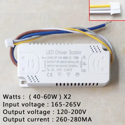
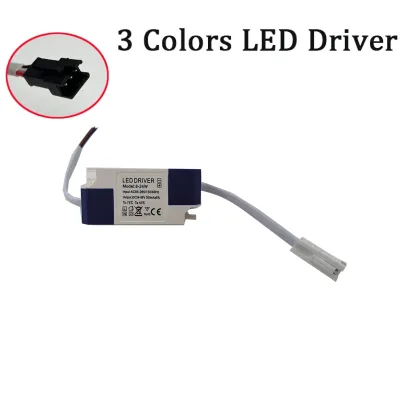
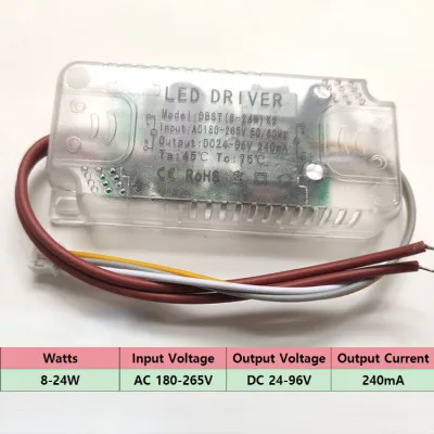
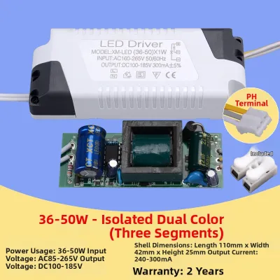
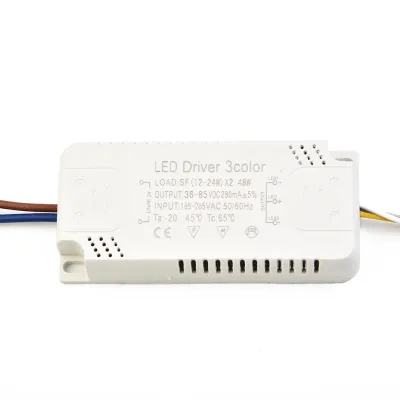
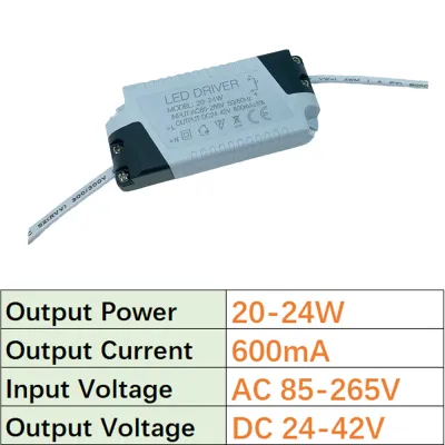
Prices are valid at publication and may change. Please refer to the product page for the latest price.
It is also essential to recognize the boundaries of safe DIY installation. If your project involves modifying fixed building wiring, running new cables through walls, or working in damp environments like bathrooms or outdoor areas, you must stop and hire a Licensed Electrical Worker (LEW) in Singapore. Furthermore, if you encounter unlabeled wires, damaged insulation, or lack a clear grounding path in your ceiling box, do not attempt to guess the connections. Professional intervention ensures compliance with local electrical safety standards and protects your home from electrical hazards.
Identifying Compatible Dimmers and Remote Receivers
Achieving smooth dimming and color temperature transitions depends entirely on matching the control protocol of your dimmer switch or remote receiver with the input requirements of the 3-color LED driver. Common dimming protocols include TRIAC (phase-cut), 0-10V, and Pulse Width Modulation (PWM). A driver designed exclusively for 0-10V analog control will not function correctly if wired to a standard TRIAC wall dimmer, resulting in severe flickering or a complete failure to illuminate. Always consult the manufacturer’s specification sheet for both devices to confirm they share a compatible dimming method.

You must also distinguish between controllers that only adjust brightness and those designed to manage color temperature (CCT) switching. Standard wall dimmers only modulate the overall power delivered to the driver to lower or raise the light intensity. If you want to change the color temperature of a 3-color LED, you need a driver that cycles through its color modes via rapid power toggling, or a specialized CCT controller that features dedicated output channels for warm and cool light. Attempting to use a basic single-channel dimmer to control color blending on a multi-channel driver without the proper interface will limit you to a single static color or cause erratic switching behavior.
Before making any physical connections, carefully study the wiring diagrams provided by the manufacturers of both the driver and the control module. Locate and identify the specific terminal labels on each device. On the input side, look for “L” (Live), “N” (Neutral), and the ground symbol. On the output or control side, identify labels such as “DIM+\” and “DIM-\” for dimming signals, or “V+\”, “CW” (Cool White), and “WW” (Warm White) for the low-voltage DC connections leading to the LED light source.
Wiring the 3-Color LED Driver to a Wall Dimmer Switch
To wire a 3-color LED driver to a physical wall dimmer switch, you must first establish the correct path for the mains power. Begin by routing the incoming Live wire from your distribution board directly to the “Line In” or “L” terminal of the wall dimmer switch. Next, connect a wire from the dimmer’s “Load Out” or “L1” terminal to the Live (L) input terminal on the LED driver. This configuration ensures that the dimmer switch successfully modulates the AC phase or voltage before the power reaches the driver’s internal conversion circuitry.
The Neutral wire from your household supply must bypass the dimming mechanism of standard analog switches and connect directly to the Neutral (N) input terminal of the LED driver. However, if you are installing a modern smart dimmer switch, it may require its own Neutral connection to power its internal wireless radios and processors. In this scenario, use an approved splicing connector to split the incoming Neutral wire, sending one branch to the smart switch and the other to the N terminal of the LED driver.
For advanced dimming systems that utilize low-voltage control signals, such as 0-10V setups, you must run a separate pair of low-voltage wires between the dimmer and the driver. Connect the positive control terminal (often labeled DIM+ or Purple) on the dimmer to the corresponding DIM+ terminal on the driver. Repeat this process for the negative control terminal (labeled DIM- or Grey). Keep these low-voltage signal wires physically separated from the high-voltage AC wiring inside the junction box to prevent electromagnetic interference from disrupting the dimming signal.
Finally, secure all wire connections tightly using high-quality, screw-type terminal blocks or spring-loaded splicing connectors. Loose connections are a primary cause of electrical resistance, localized heating, and intermittent power loss. Ensure that the safety ground wire from your home’s electrical system is securely bonded to the green or yellow-green ground terminal on both the dimmer switch and the LED driver’s metal housing, if applicable, to provide a safe path for fault currents.
Connecting a Remote Control Receiver Module
Integrating a wireless remote control receiver module allows you to adjust both brightness and color temperature without relying on physical wall controls. The wiring configuration depends on whether the receiver operates on the high-voltage AC side or the low-voltage DC side of the circuit. For most residential 3-color setups, a DC-side receiver is preferred because it allows precise, independent control over the individual warm white and cool white LED channels downstream of the driver.
To wire a DC-side remote receiver, first connect the AC mains Live and Neutral wires directly to the input terminals of your 3-color LED driver. Next, run the positive and negative DC output wires from the driver (typically labeled V+ and V-) to the corresponding DC input terminals on the remote receiver module. From the output side of the receiver, connect the common positive wire (V+) to the positive terminal of the LED fixture, and connect the individual negative channels (often labeled WW for warm white and CW for cool white) to their respective terminals on the light fixture.
Proper physical placement of the remote receiver is crucial for maintaining a stable wireless connection. Avoid mounting the receiver inside a fully enclosed metal junction box or behind dense structural materials like concrete, brick, or thick plasterboard, as these materials severely attenuate radio frequency signals. If the receiver features an external wire antenna, extend it fully and position it away from other electrical cables to minimize signal interference and maximize the operational range of your remote control.
Before mounting the fixture permanently and sealing the ceiling cavity, you must pair the remote control with the receiver module. Restore power to the circuit at the distribution board, then follow the manufacturer’s specific pairing sequence. This process typically involves pressing and holding a “Pair” or “Sync” button on the physical receiver, or pressing a specific button combination on the remote control within a few seconds of powering on the system. Verify that the remote successfully controls the light before completing the physical installation.
Testing the Circuit and Troubleshooting Common Issues
Once all physical connections are secure and insulated, you can safely proceed to test the completed circuit. Restore power at the main distribution board and turn on the wall switch or remote control. Slowly adjust the dimmer from its lowest setting to its maximum brightness, observing the light output for any signs of instability. Next, cycle through the color temperature settings to ensure the driver transitions smoothly between warm white, neutral white, and cool white without any sudden dropouts or color shifts.
If you observe flickering, strobing, or a high-pitched buzzing sound, these are common symptoms of electrical incompatibility or poor connection quality. Flickering often occurs when the minimum power draw of the LED driver falls below the minimum load requirement of the dimmer switch. To resolve this, check if your dimmer switch features a physical trim dial, which allows you to adjust the lowest voltage threshold to a level where the driver remains stable. If the buzzing persists, verify that the driver is mounted securely to a solid surface, as loose mounting brackets can amplify normal electrical vibrations into audible noise.
You must be prepared to take immediate action if you encounter critical electrical faults during testing. If you detect a burning odor, see smoke, observe the driver or dimmer becoming hot to the touch, or if the circuit breaker trips immediately upon restoring power, turn off the power at the distribution board without delay. These symptoms indicate a short circuit, severe overload, or catastrophic component failure. Do not attempt to turn the power back on; instead, leave the circuit isolated and contact a licensed electrician to diagnose and repair the system.
Frequently Asked Questions (FAQ)
Can I use a standard incandescent dimmer with a 3-color LED driver?
No, you should never use a standard incandescent dimmer switch with a 3-color LED driver. Legacy incandescent dimmers are designed for high-wattage resistive loads and typically use leading-edge phase-cut technology, which is highly incompatible with the sensitive capacitive circuitry of modern LED drivers. Attempting to use an incompatible dimmer will result in severe flickering, a restricted dimming range, audible buzzing, and can permanently damage the internal components of both the driver and the LED light fixture. Always select a dimmer switch that is explicitly certified for LED loads, preferably a trailing-edge or universal electronic dimmer.
Does the remote receiver replace the LED driver entirely?
A remote receiver does not automatically replace an LED driver unless it is specifically designed and labeled as an integrated smart LED driver. Standard remote control receivers are control modules that modulate existing electrical current; they do not convert high-voltage AC mains power (220V-240V) down to the safe, low-voltage DC power (typically 12V, 24V, or constant current) required by LED chips. You must check the input voltage specifications printed on your receiver module. If the receiver specifies a low-voltage DC input, it must be installed downstream of a separate, compatible LED driver to prevent destroying the receiver and creating a severe electrical hazard.

Community discussion
Share your experience or ask a question. Comments are reviewed before publication.