
Choosing the correct led strip connector is essential for a reliable, flicker-free DIY lighting setup. When installing a dimmer switch or remote controller, you will find there is no single universal plug. A mismatch can lead to loose connections, short circuits, or damaged components. To get your connection right the first time, you must align the physical characteristics of your LED strip with the specific output interface of your controller.
Decoding LED Strip Specs: Pins, Pitch, and Gender
Before looking at your controller, you must understand the connection points on your LED strip. The strip features flat copper pads along its cut lines, which serve as the electrical contact points. The number of these pads, their spacing, and the physical width of the strip dictate the type of connector you need.
Pin Count The number of copper pads determines the pin configuration of your connector. This must match exactly to ensure every channel receives the correct electrical signal:
Products mentioned in this guide
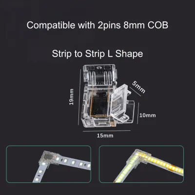
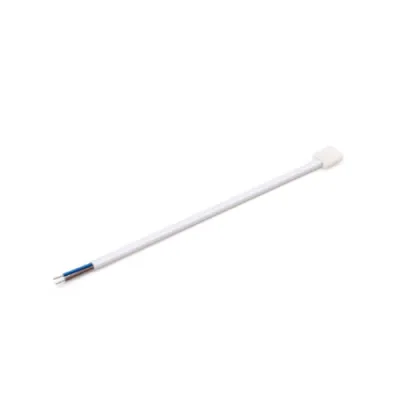
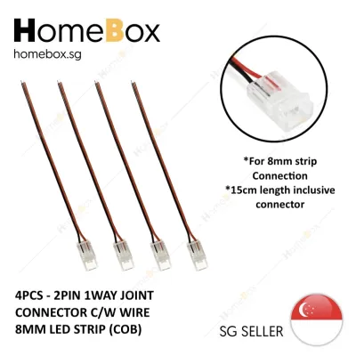
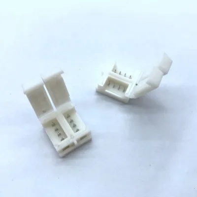
![[SG Local Seller] LED Strip Light Connector COB Connector 10mm 8mm](https://img.lazcdn.com/g/p/6d85efb90fc080906de23f4f27adcf6c.jpg_400x400q80.jpg_.webp)
![[SG Local Seller] COB Connector Strip Light Connector with Wire End Corner L Joint 8mm](https://img.lazcdn.com/g/p/aabcdec7869a033619e295bb5427ce9c.png_400x400q80.png_.webp)
Prices are valid at publication and may change. Please refer to the product page for the latest price.
- 2-Pin: For single-color LED strips (positive and negative lines) or basic adjustable white systems.
- 3-Pin: Standard for addressable (ARGB) strips (power, data, and ground) or specific dual-color CCT strips.
- 4-Pin: The standard for RGB multi-color strips (common anode power line plus individual red, green, and blue channels).
- 5-Pin: Typically used for RGBW strips, which add a dedicated white channel. Some advanced RGBCCT strips may require 6-pin configurations.
Pitch and Width The physical width of the LED strip is just as critical as the pin count. LED strips commonly come in widths of 8mm, 10mm, or 12mm. The connector you choose must match this width exactly. If you try to slide a 10mm strip into an 8mm connector, it will not fit. Conversely, using a 10mm connector on an 8mm strip will cause the internal metal pins to misalign, potentially bridging adjacent copper pads and causing a short circuit.
Gender (Male vs. Female) You must also identify the physical connection interface at the end of your strip. “Male” connectors feature exposed metal pins, while “Female” connectors feature recessed sockets. If your LED strip has a pre-soldered cable ending in a female plug, you will need a male connector to mate with it. If you are starting with a freshly cut strip, you will typically use a solderless clip-on connector that clamps directly onto the bare copper pads.
Actionable Step: Use a precise ruler or caliper to measure the exact width of your LED strip across its cut line and count the copper pads before purchasing any connectors.
Identifying Your Dimmer or Controller Output Port
Once you have identified your LED strip specifications, you must inspect the output interface of your dimmer or remote controller receiver. Dimmer units come with various port styles, each requiring a specific connection method.

Screw Terminal Blocks Often found on professional-grade wall dimmers, DMX decoders, and high-capacity multi-channel controllers, screw terminals feature small slots where wires are inserted and secured with a screw. These do not accept plug-and-play pin connectors. Instead, you must use a connector with a solderless clip on one end (for the strip) and bare, pre-stripped pigtail wires on the other.
DC Barrel Jacks Commonly found on simple, single-color inline dimmers and compact RF receivers, these circular ports typically measure 5.5×2.1mm. Since you cannot plug an LED strip directly into a circular jack, you will need a matching DC male or female adapter to bridge the barrel jack to the bare wires of your strip connector.
JST/SM Plastic Connectors These latching plastic housings are highly common on addressable (ARGB) pixel controllers. They provide a secure, click-lock connection that prevents accidental disconnection. Because their plastic shapes and pin configurations are not universally standardized, you must verify that the housing shape of your controller’s plug matches your connector exactly.
Standard Pin Headers Many standard RGB and ARGB controller boxes feature exposed male pin headers. These require a matching female pin connector, which is often pre-molded onto a flat ribbon cable or a solderless clip adapter.
Actionable Step: Physically inspect the output ports on your controller or check its manufacturer manual to confirm the port type before buying any adapters or connector cables.
Bridging the Gap: Matching Connectors and Adapters
When the physical interface of your LED strip does not natively match the output port of your controller, you must use adapters or wiring techniques to bridge the gap safely.
Direct Matches In ideal setups, both your LED strip and your controller share the same standard interface. For example, if your RGB strip has a pre-installed 4-pin female connector and your controller features a 4-pin male header, you can plug them directly into each other. Ensure you align the polarity markers (usually indicated by a small arrow on the plastic housing).
Using Adapters If your ports do not match, adapters are the cleanest solution. For example, if your controller has a DC barrel jack but your single-color strip has bare wire ends, you can use a “DC female to screw terminal” adapter. This allows you to secure the bare wires into the screw terminals on one side while plugging the DC barrel jack into the other.
Wire Splicing and Terminal Blocks When preparing bare wires for screw terminals, strip exactly 5mm to 7mm of insulation from the wire ends. Twist the copper strands tightly together so there are no stray wires, or crimp them with wire-end ferrules. Loose copper strands sticking out of a terminal block can touch adjacent terminals, causing a short circuit, sparks, or permanent damage to the controller.
Quick Connection Reference The table below outlines common LED strip configurations and the standard adapter solutions required to connect them to different controller outputs:
| LED Strip Type | Controller Output Port | Required Connector / Adapter Type |
|---|---|---|
| Single Color (2-Pin) | DC Barrel Jack (5.5×2.1mm) | 2-pin solderless strip connector to DC female adapter |
| Single Color (2-Pin) | Screw Terminal Block | 2-pin solderless strip connector to bare pigtail wires |
| Standard RGB (4-Pin) | 4-Pin Male Header | 4-pin female-to-female extension cable |
| Standard RGB (4-Pin) | Screw Terminal Block | 4-pin solderless strip connector to bare pigtail wires |
| Addressable (3-Pin) | 3-Pin JST/SM Plug | 3-pin JST/SM male/female connector set |
Physical Limitations Keep in mind that plastic clip-on connectors, terminal blocks, and adapters add physical bulk to your installation. If you plan to mount your LED strips inside shallow aluminum profiles or tight architectural recesses, these bulky connectors may not fit. In tight spaces, soldering wires directly to the strip’s copper pads is often the only way to maintain a low-profile installation.
Critical Safety Checks Before You Connect
Before powering on your newly connected system, you must perform several critical safety and electrical checks. Skipping these steps can lead to component failure, electrical shorts, or fire hazards.
Voltage Verification Connectors and adapters are passive metal and plastic components; they do not regulate or convert voltage. You must verify that the output voltage of your power supply and controller (typically 12V or 24V) matches the rated voltage of your LED strip. Connecting a 12V LED strip to a 24V controller will instantly burn out the strip, while connecting a 24V strip to a 12V controller will result in extremely dim light or no operation at all. Always check the manufacturer labels on all devices.
Pinout and Polarity Alignment Do not assume that wire colors or pin orders are standardized across different brands. Always look at the printed labels on the LED strip (such as “V+”, “GND”, “R”, “G”, “B”) and align them with the corresponding labels on your connector and controller. Reversing the positive power line (V+) with a ground or data line can permanently destroy the controller’s internal circuitry and the LED chips.
Current and Wattage Limits Ensure that your controller, power supply, and the physical wires of your connectors are rated to handle the total current (amperage) and wattage of your LED strip. Overloading a thin connector wire with too much current can cause the plastic to melt, posing a severe fire hazard.
Pre-Connection Rule Always isolate the main power supply (unplug the power adapter or turn off the circuit breaker) before cutting, connecting, or adjusting your wiring. Always consult the manufacturer’s official wiring diagrams for both the LED strip and the controller. If your installation involves fixed electrical wiring, working at height, or damp environments, ensure you isolate the power and consult a qualified professional to complete the installation safely.
Frequently Asked Questions (FAQ)
Can I plug a 4-pin RGB connector into a 3-pin ARGB controller?
No, you cannot. Even if you manage to force the physical connection, standard RGB and addressable RGB (ARGB) systems operate on completely different electrical and signal standards. Standard RGB strips use analog control and typically run on 12V or 24V, where all LEDs on the strip change color simultaneously. ARGB strips use digital data signals to control individual LEDs and typically operate at 5V. Attempting to mix these systems will send incorrect voltages to the digital data lines, instantly frying the addressable IC chips on the strip or destroying your controller. Always use matching 3-pin connectors with a compatible ARGB controller.
Do I need a different connector for waterproof (IP65/IP67) LED strips?
Yes, waterproof LED strips require special handling. Standard solderless clip-on connectors are designed for non-waterproof (IP20) strips and cannot pierce or grip through thick silicone coatings or protective sleeves. To connect a waterproof strip, you have two options. First, you can use specialized waterproof connectors equipped with sharp metal teeth designed to bite directly through the silicone layer to make contact with the copper pads. Second, you can use a utility knife to carefully peel away the silicone coating from the copper pads, exposing the bare metal so you can use a standard connector. Note that stripping the silicone compromises the waterproof rating at that joint; you must reseal the connection using heat-shrink tubing and outdoor-rated silicone sealant to maintain moisture protection.

Community discussion
Share your experience or ask a question. Comments are reviewed before publication.